This chapter gives an overview of the modeling surface of the application. Figure 1 shows an overview of the modeling surface.
The areas marked by numbers are explained in detail below.
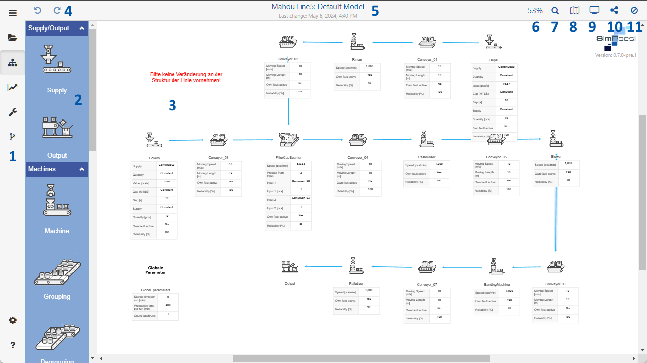
Figure 1 - Modeling space
On the left side of the application there is the menu. Details about the menu can be found in the chapter Menu Bar.
The toolbox contains a variety of simulation objects. These can be dragged to the right onto the modeling surface by Drag’n’Drop to create a model.
A description of the individual simulation objects can be found in the chapter of the Objects of the toolbox for simulation. How to handle with the simulation objects can be found in the chapter Handling simulation objects.
The largest space of the application is available for modeling. Models can be created and managed here. Instructions can be found in the chapter Handling simulation objects
Zoom Functionality
In the desktop version of the application it is possible to zoom in while holding down the [CTRL] key and simultaneously moving the mouse wheel in the toolbox.
In the tablet or smartphone version, this functionality can be accessed via the standard zoom gesture (see Figure 2 and 3).
Figure 2 - Zoom in |
Figure 3 - Zoom out |


These two buttons can be used to undo or repeat actions that have been performed, such as inserting objects.
Changes to parameter settings are not affected by this action.
The name of the currently selected project and the currently selected alternative is displayed here ("Project name": "Alternative name").
The time of the last change in the modeling interface is always displayed below.
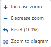
By clicking on the percentage value, different zoom settings can be performed, as shown in the below figure.
By clicking on the magnifying glass icon, objects can be searched for via a dialog.
The figure opposite shows the dialog with the drop-down menu open, which contains all the objects used on the modeling surface.
As soon as an element has been selected and the search has been started via the Search button, the corresponding element is then selected on the modeling surface and this is centered on the respective object.

This button can be used to show or hide an overview window that helps to keep an overview of the entire modelling, especially for larger simulations.
The button displays a drop-down list where you can specify the level of detail in which the parameters of the objects should be displayed.
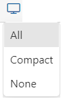
Optionally, the parameter display can also be changed by double-clicking on a free space in the modeling area.
The following views are available:
•Display: All
•Display: Compact
•Display: None
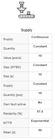
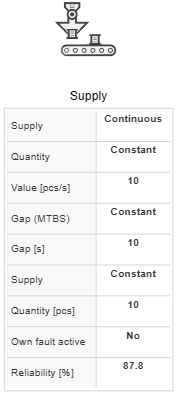
Figures 4-6 show an example of a parameter view.
Figure 4 - Display all |
Figure 5 - Display compact |
Figure 6 - Display none |
Using the button, the currently selected alternative can be either printed or exported as an image (*.png) or as SVG.
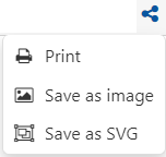
Save as image/SVG
To export as image (*.png) or as SVG, simply select the corresponding entry in the dropdown. Then Windows Explorer opens and the file can be saved.
Printing alternatives
Clicking on Print opens a dialog where the alternative can be printed with the available printers or saved as a PDF.
Using the button, it is possible to select elements via a dropdown that are to be hidden on the modeling interface.
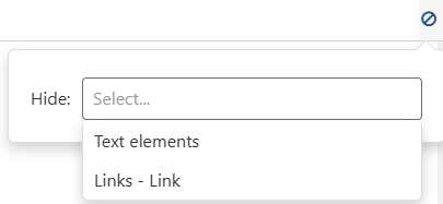
Figure 8 - Hide elements
© SimPlan AG - Hanau District Court, Commercial Register (Part B) 6845 - info@simplan.de - www.simplan.de/en