Contents
The symbols described here for the parametrization of objects are the same for all simulation objects. The following table lists the existing symbols and explains them:
Button |
Description |
|
Opens the Icon Editor. Here the icon can be rotated or mirrored or a alternative icon can be choosen. Also, a custom size can be set for the icon.
Figure 1 - Icon editor |
|
Deletes the object |
|
First click defines the object as measurement start point Second click defines the object as measurement end point Third click defines the object as measurement start and end point Fourth click removes the previously created measuring points from the object |
|
Opens the editing menu of the object. Detailed instructions for this menu can be found in the chapter Editing simulation objects |
|
Opens a dialog in which either a picture can be taken with the help of a webcam, or an image can be loaded from Windows Explorer.
Figure 2 - Camera dialog |
|
Opens the photo gallery of the object. Photos that were previously created are displayed here.
Figure 3 - Add Photos With the option Show in Model, photos can also be displayed and arranged directly in the modeling interface (see Figure 5). Furthermore, the anchor at the lower right edge can be used to adjust the size of the image. |
|
Hides extended product information/images (if displayed) |
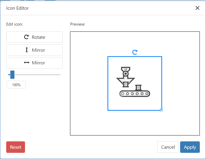

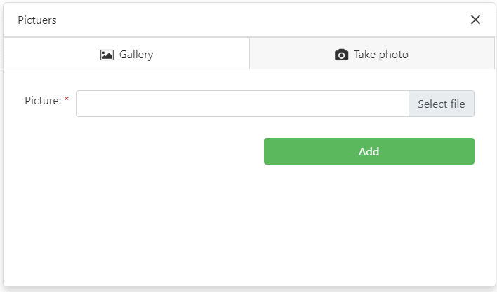
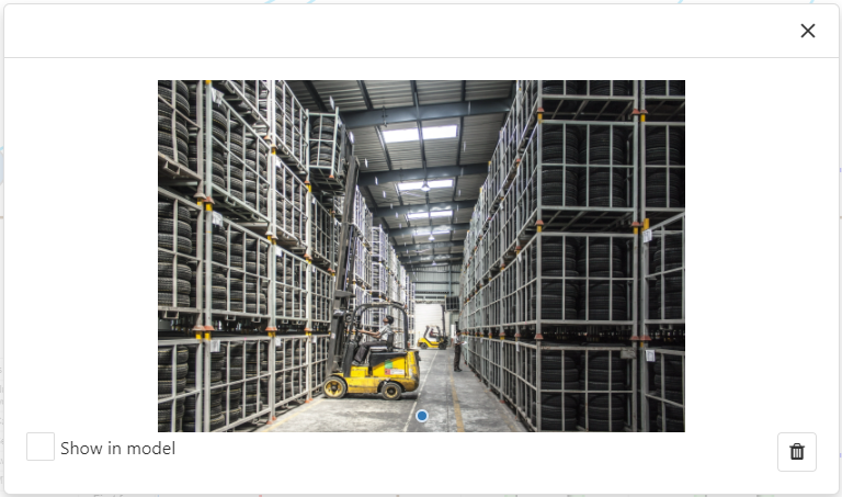
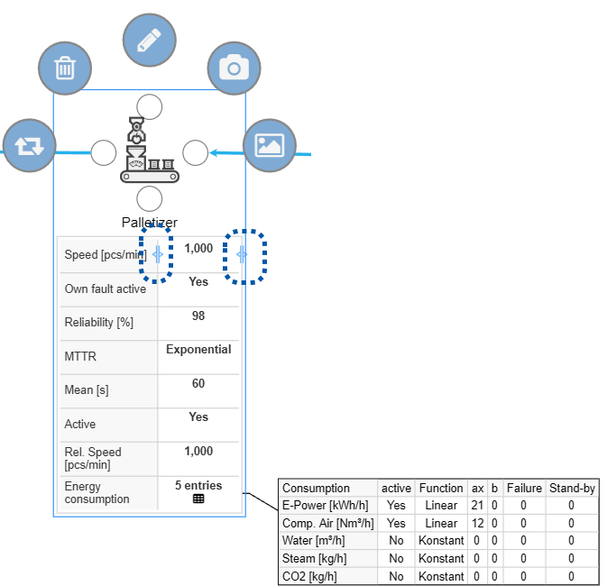
Figure 4 shows a customer object with the respective object symbols.
Furthermore, if defined for the object, a detail window containing information about the respective product can be displayed by clicking on the product name.
The size of the parameter window can be adjusted using the slider (see marking in Figure 3).
Figure 4 - Object symbols customer object |
Figure 5 - Show images in the modeling interface |

External links can be added to the text item via the input field. This can be a hyperlink (link to a website) or a network link (link to a local file).
As soon as a valid link has been entered in the input field (see Figures 1 and 2), it will be displayed behind the content of the text item after closing the page menu (see Figure 3).
The link can now be called up with a mouse click. The dialog box from Figure 4 then appears, in which it must be confirmed once again that the corresponding link is to be called up.
Figure 1 - Input field |
Figure 2 - Error message |
Figure 3 - Result |
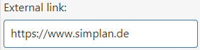
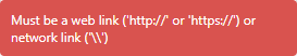
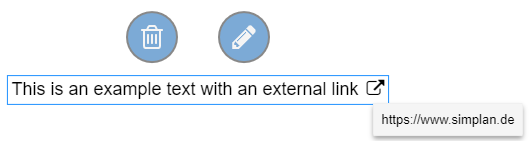
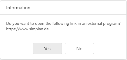
Figure 4 - Info dialog
© SimPlan AG - Hanau District Court, Commercial Register (Part B) 6845 - info@simplan.de - www.simplan.de/en